
The Sound Card and How it Works
For a ham radio operator trying to work the digital modes for the first time, half the battle is installing the software and learning how to make it work. The other half of the battle is installing the Sound Card, making all the right adjustments, and trying to make that work successfully. However, if you have one of the newer ICOM, Yaesu, or Kenwood radios, that struggle is almost eliminated as they have their sound cards built-in.
But, if your transceiver doesn’t have one, you’ll need to come up with something that takes the audio from the computer and run it into the radio; and then from the radio and back into the computer.
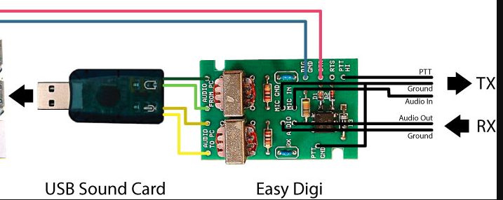
As shown above, the cheapest way to deal with this is to buy a USB audio dongle from eBay for about $ 3 and then a sound card kit for about 10 bucks. And finally, you’ll need to purchase a few 3.5 mm cables to connect from the dongle to the sound card. Then the fun begins, trying to figure what cable goes to where.
Inside the Sound Card
Essentially, a sound card is a device that takes the audio produced from the computer, matching the impedance between the computer and the radio and attenuating the signal considerably. Otherwise, the audio signal would be too strong for the radio to work properly, overloading the distorting it. Likewise, when sending a signal back from the radio to the computer, the audio has to be controlled and the impedance matched between the two pieces of hardware.

The schematic above shows the audio coming from the USB dongle into a resistor divider network, at R3 and R4, which steps down the signal by 100 to 1. Then the audio goes through T2 for impedance matching. At the input and output to T2, there are capacitors used for shaping the signal going from the computer to the radio.
Going from the radio back to the computer, the schematic is similar; it uses a transformer, T1, used for impedance matching.
On better sound cards, potentiometers are used for further adjustment for the inputs and outputs.
Some sound cards provide for the capability of operating the PTT circuit by taking the control signal off the DB 9 connector on the computer and sending it to an optocoupler on the sound card. This is used to separate any difference of potential which might exist between the two pieces of hardware.
A Better Solution
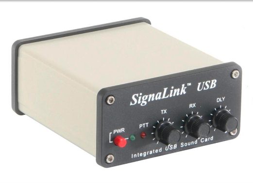
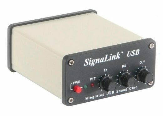
Of course, the easiest way to deal with this is to purchase something like the Signalink USB card from a supplier such as Ham Radio Outlet for about $ 125. The advantage to this card is that it plugs directly into the USB connector on your computer – eliminating the USB dongle – and then connects to the radio with a special DIN connector at the other end. Also, this card has individual controls for TX, RX, and Delay.
Final Adjustments
Enough can’t be said about the need to make sure the right audio levels are set for the inputs and outputs at the computer and the radio. If the audio is too strong going into the radio, your transmission will distort, making QSOs harder to get. And at the other end, if the input signal is not at the proper level to the computer, the software will not be able to pick up the incoming sound.
My hope here is that with a little understanding of the sound card and what it does, this will make your next QSO on one of the digital modes as smooth as possible. With some trial and error worked out, your next contact will be a lot easier. 73
Randall N1KRB
Thanks Randall,
What are the typical impedance values that the transformers are trying to match on the input pair and similarly the output pair.
73 de k1jbd
Greetings – and thanks for your question. When the audio goes from the speaker out on the computer to the radio line level in, the impedance is about 8 ohms at the output to 1K on the radio input.
The transformer is used to help match the impedance as well as provide ground isolation between the two chassis. The real issue is controlling the signal strength at the computer output which is about 1v p-p, while the radio input will accept a signal in the millivolt level.
Watch your meter to keep the outputs and inputs in the linear range. Refer to YouTube video by K7AGE. 73 – N1KRB
Great explanation and easy to follow how sound cards work for digi transmissions. You’re a big benefit to better understanding what goes on inside that magic box. BTW, been on FT8 for a month and love it. 73 from Brookline. Dennis K1LGQ
Nice article Randall,
To dig into the inteface a bit further I suggest reviewing the data sheet for the Ti PCM2904 USB/CODEC that is used in the SignaLink. Icom and Kenwood radios with a built in USB/CODEC both use devices from the same Ti PCM290X device family.
Thanks for the info, Hamilton. I did look at the data sheet and very interesting to see how they handle the signals. It goes from the USB and keeps all the signals digital until the DACs for the input and outputs to the radio. Great to know.
Thanks for the comment, Dennis. The reason I wrote this article is that the basics of a sound card are easy to understand; and with a little knowledge, the ham will take the time to make sure the input and outputs levels are set right in order to not over modulate the signals … or send enough signal to the computer for the software to decode the signal. At your recommendation, I tried FT4 and now doing a lot of PSK31. Talk to you soon – 73 N1KRB
Good article Randall. I love it when someone takes a tech subject and makes it understandable for the average guy ( thats me). I will drop off the Signalink to you this week.
Patrick, W1YTT in Loverly Downtown Nashua
Hi Average Guy – thanks for your comments. From doing this article, I learned a lot about something so little. I was a lot of fun to do. Pat – I look forward to seeing you soon. 73 N1KRB