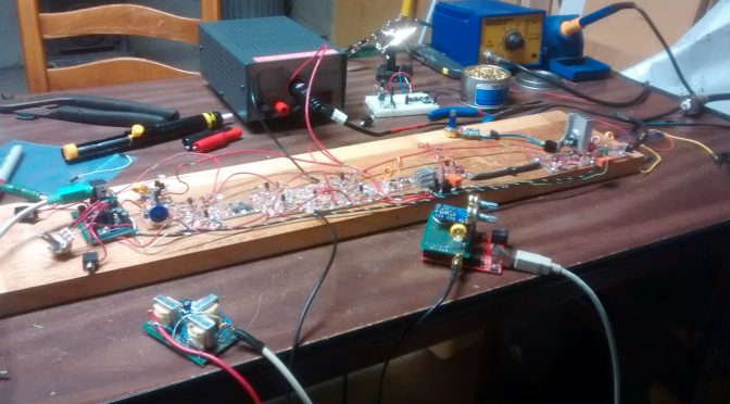
About a year ago I decided to build an SSB transceiver for making contacts with other amateur radio operators on the HF bands. I was given good advice from both Bill and Pete from the SolderSmoke Podcast to start out with a direct conversion receiver then go with the BitX20 as a first SSB rig. I am very happy that they gave me that advice and I would agree that the BitX is not a good first project.
After getting all the proper adjustments made and confirming proper operation with a dummy load it was time to put this rig on the air (I don’t need a case)! I tried calling CQ using SSB voice but no one came back. I then decided to add some relays and other modifications to allow digital modes.
On January 15, 2017, at 21:46z I answered a psk31 CQ from Josh K1JOG in Kissimmee, FL. Little did he know that he would be making history (maybe just for me) in my first home brew QSO. Below is his eQSL card to me.

If you are interested in scratch building this rig you can follow the photo link below:

Ashhar Farhan also sells a BitX40 at http://www.hfsigs.com/
The units he has built in India are almost ready to put on the air. You build the case/box or just go open board style! You can’t beat the $59 price for a rig!
Below are some photos of my project:
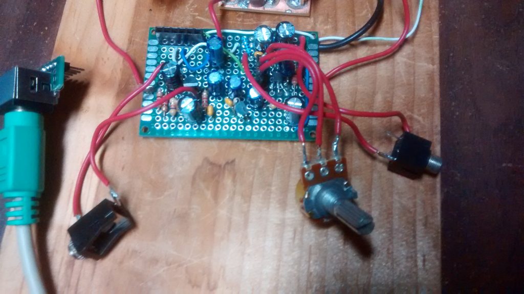
A good place to start is the Audio “end”. I built mine using perf prototype board. FYI the 10k ohm resistor on the mic amp needs to be 39k ohm for proper bias.
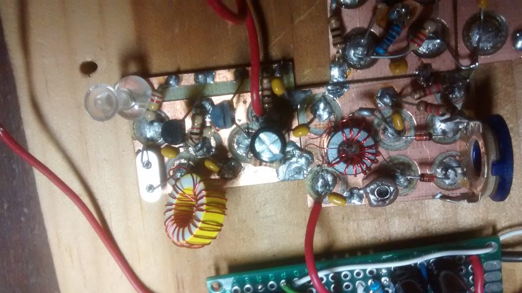
On the balanced modulator, I used a mystery toroid core because I have a bunch of them and they did not cost much!
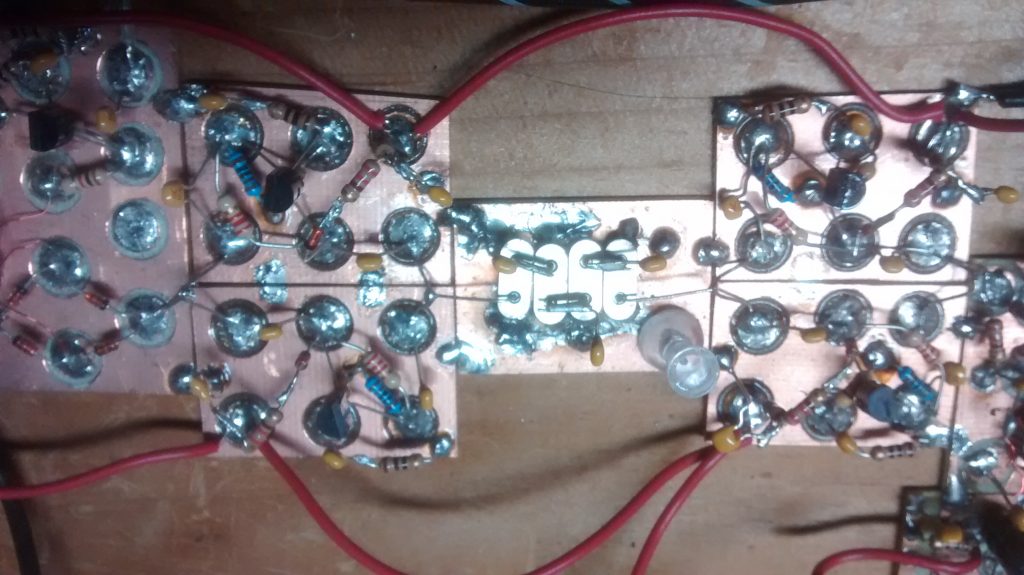
In this photo, you can see some transmit and receive amplifiers and the crystal filter. I built some test equipment and used a frequency counter to make a matched set of crystals.
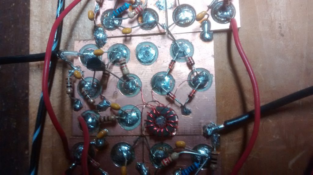
The mixer circuit is shown here with some coax to the left that is from the VFO.
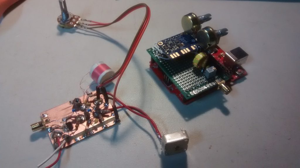
You can see the benefit of building small modules. With SMA connectors, I can quickly swap out the VFO “soul” of this rig! No more drift with the SI5351 chip! I ordered mine from Adafruit. I added a small LC filter to the output to make a nice sine wave. I am not sure it is needed.
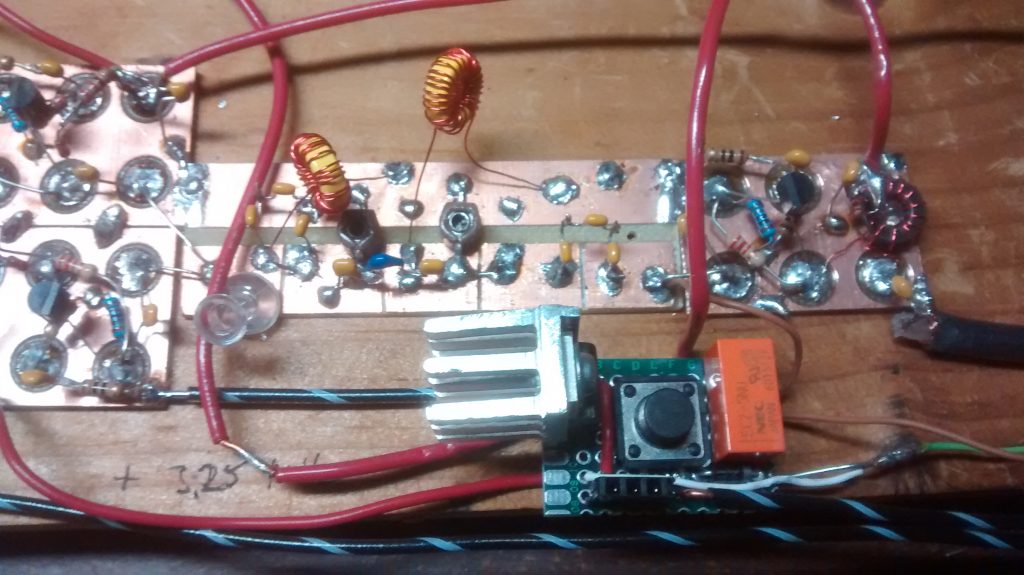
Now I had trouble with the original band pass filter. I’m not sure why but a quick google search on 20m band pass filter and I found a replacement circuit on his website. When I told Pete about this he sent me a new updated design to try. My PTT relays are 5v so the small heatsink is for the voltage regulator. I also included diode protection for the replays.
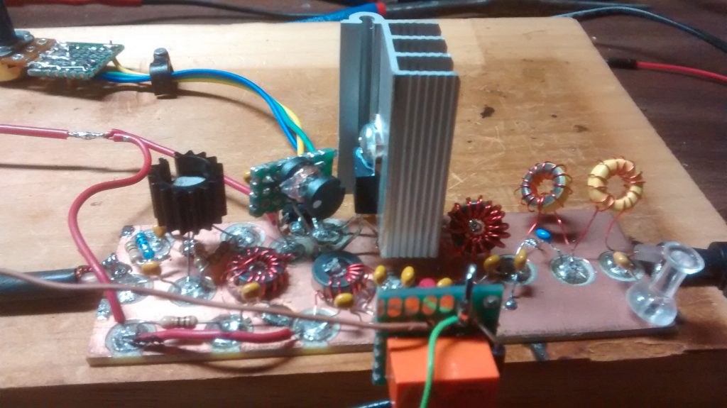
The IRF510 is more of a switch and not designed for linear RF amplification but it is cheap and works great for QRP. They have different bias requirements from one unit to the next. That is why you carefully set the bias level with a trim pot. The large heat sink was part of an old high power LED driver that died. I used T37-6 toroid cores for the low pass filter on the right. The 2nd relay was needed to prevent the output of the IRF510 feeding back into the original PTT switch and back into a nasty loop.
I am not sure if this rig will ever get a case or future modifications but I do know that I would like to see if I can make more contacts with it.
I would like to end this article with a quote I very much like from a video with Rev. George Dobbs, G3RJV
“Radio construction is rather like a pilgrimage where the journey is often more important than the destination”.
73,
Mike, AB1YK

