Nashua Area Radio Society › Topics In All Forums › Mentoring Forum › Mounting Antennas on a Tower
- This topic has 1 reply, 1 voice, and was last updated 6 years, 11 months ago by
 Fred Kemmerer.
-
AuthorPosts
-
December 20, 2018 at 12:58 pm #64724
[caption id="attachment_64709" align="aligncenter" width="1024"]
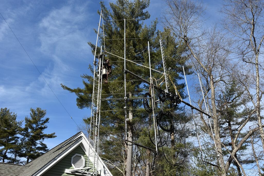 Tramming Satellite Antennas[/caption]
How do you get a complex antenna system like a Satellite Array up on your tower? One way to do it with a tram line. The picture above shows our satellite antennas going up on our new, house-bracketed tower. We let the mast down into the tower to make the process easier and we used a Gin pole at the top of the tower to support and elevate one end of the steel tram line. The key to this process is to get the harness that attaches the antenna system to the tram line perfectly balanced. Matt Strewlow, KC1XX and Andrew Toth did the installation here yesterday.
[caption id="attachment_64710" align="aligncenter" width="682"]
 Antennas on the Tower[/caption]
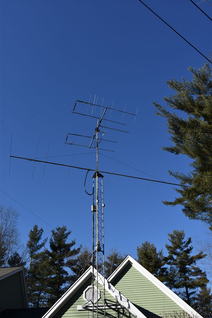
We also put a new 7 element 6m yagi on the tower as well. The picture above shows the completed installation. There are actually two rotators in this setup. An Alfa-Spid Az/El rotator on the top of the mast points the Satellite Antennas and an M2 Orion in the tower turns the entire mast assembly which points the 6m yagi.
[caption id="attachment_64711" align="aligncenter" width="682"]
 Satellite Array[/caption]
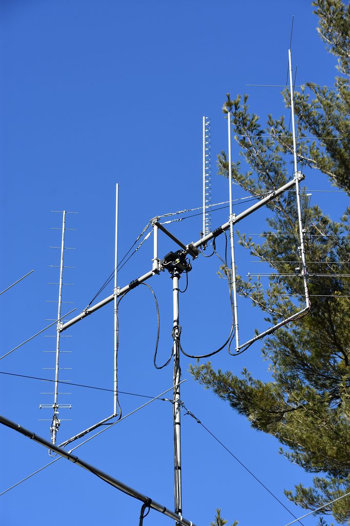
Here a closeup picture of the satellite array. It handles 3 bands – 2 m, 70 cm, and 23 cm. This is the same setup that we’ve been using a Ham Fests and for the primary station for our recent ISS Crew Contact. The cross-boom system was totally rebuilt to include a truss support system and polycarbonate plugs to reinforce the fiberglass cross-boom. The final system is much strong than the portable version.
There is quite a bit of integration work with the rest of the station here to get everything working and there will be, no doubt, some early life problems to solve given the complexity of all of the new gear. I plan to post some articles in the near future with more details on steps we took to get to this point as well pictures and info as we work through the integration steps.
We’re looking forward to using our new antennas soon!
Attachments:
You must be logged in to view attached files.December 20, 2018 at 1:04 pm #64727[caption id="attachment_64726" align="aligncenter" width="1024"]
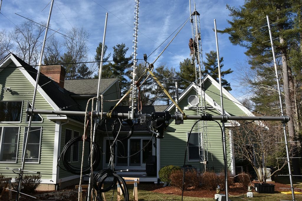 Tram Line and Harness[/caption]
Here’s one more picture which shows the tram line and harness. Note how well balance the entire setup is. The feed lines for the three antennas and the control cables for antenna polarity switch and the Alfa-Spid Az/El rotator are also attached. All of this prep work is much easier to do on the ground. You can also see one of the two truss supports which were added to transfer the weight of the antennas on the ends of the cross boom to the center.
-
AuthorPosts
- You must be logged in to reply to this topic.