General coverage short-wave receivers may lack preselection against strong AM broadcast stations, and these broadcast stations may overload the receivers. SDR receivers, particularly the USB type[1], that plug into your computer are examples of this receiver type.
When I was designing my 10-band QRP transceiver, I wanted to incorporate an AM notch filter into the receiver for general coverage. In this mode of operation, the bandpass and lowpass filters are bypassed leaving the front end of the receiver wide open.
Since there are no FM broadcast transmitters nearby, I chose to include a notch filter for AM only because the receiver gain in my QRP transceiver from 88 to 108 MHz is greatly attenuated.
Rather than design and build a suitable notch filter, I looked for a suitable commercial off-the-shelf (COTS) product that I could package into what I wanted. The solution was the Nooelec Flamingo+ AM – High Attenuation Broadcast AM Bandstop (Notch) Filter[2].
My transceiver is based upon the N3FJZ software and hardware architecture [3], and Rick’s software architecture provides for general coverage whenever the receiver is tuned to other than one of the 10 designated ham bands. Thus, under these conditions, all of the filters in the transceiver are switched to bypass mode. I made use of this feature to incorporate the Nooelec Flamingo+ AM Notch filter in the bypass path.
Should I decide to incorporate an FM notch filter into the design in the future, the Nooelec Flamingo+ AM notch filter is easily disconnected from the printed circuit board carrier, and it may be replaced with a Nooelec Flamingo+ FM – High Attenuation Broadcast FM Bandstop Filter [4].
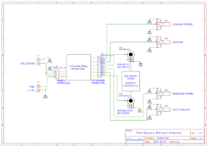
The schematic of what was built is shown in Figure 1. Optically coupled, 2-channel Arduino relays[5] are employed. When a bypass command is asserted in software, the receiver RF is routed around the bandpass and lowpass filters in the transceiver when it is in receive mode, only, i.e., the bypass does not function when the transceiver is in transmit mode.
Figure 1. Filter Bypass With BCI Notch Schematic. When the software command is asserted to place the transceiver in bypass mode, the relay modules will bypass the bandpass and lowpass filters in the receive path and insert the Nooelec Flamingo+ AM – High Attenuation Broadcast AM Bandstop (Notch) Filter. Since the AM BCI notch filter is connected to the PCB with right angle SMA connectors, it may be replaced by an FM BCI notch filter, as desired. Please click on the figure to enlarge it.
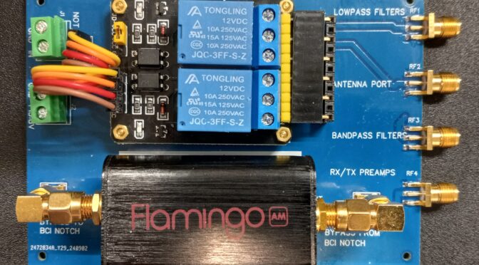
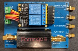
A printed circuit board, Figure 2, was designed as a carrier for the optically coupled relays and AM BCI notch filter. Pin headers are used for all connections to the 2-channel relay modules. Dupont[6] wires provide easy interconnects for power and logic inputs while pin headers are used for relay connections into and out of the printed circuit board. Dupont wires may be homebrewed with suitable component parts and a crimping tool, or they may be purchased at predetermined lengths.
Figure 2. As-Built AM BCI Bypass Printed Circuit Board. The AM notch filter may be replaced by an FM notch filter of similar form-factor by disconnecting the right-angle SMA connectors. Please click on the figure to enlarge it.
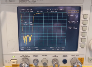
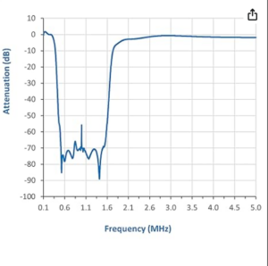
Finally, the response of the Nooelec Flamingo+ BCI Notch was measured on a spectrum analyzer with integral tracking generator. The result obtained is shown in Figure 3. The measured notch depth is close to 70 dB over most of the AM broadcast band. This result compares favorably with the plot provided by Nooelec[7] in Figure 4.
Figure 3. Measured Nooelec Flamingo+ AM BCI Notch Depth. The performance of the AM BCI Notch printed circuit board was measured on a spectrum analyzer with integral tracking generator. The notch depth is approaches 70 dB over most of the AM band. Please click on the figure to enlarge it.
Figure 4. Nooelec Data. The plot found in the Nooelec data sheet compares favorably with the measured data of Figure 3. Reproduced with permission from Nooelec. Please click on the figure to enlarge it.
Anyone wishing to duplicate this printed circuit board may contact me for a Gerber file. I will not be offering any printed circuit boards.
References:
1. https://www.nooelec.com/store/sdr/sdr-bundles/hf-bundles.html
2. https://www.nooelec.com/store/sdr/sdr-addons/flamingo-plus-am.html
3. http://www.remmepark.com/circuit6040/MAX-SSB/MAX-SSB.html#110
4. https://www.nooelec.com/store/sdr/sdr-addons/flamingo-plus-fm.html
5.https://www.amazon.com/gp/product/B081MVCS8F/ref=ppx_yo_dt_b_search_asin_title?ie=UTF8&psc=1
7. https://www.nooelec.com/store/sdr/sdr-addons/flamingo-plus-am.html. Op cit.

