
Introduction
L-matching networks provide an efficient means of feeding end-fed half-wave antennas. The advantages of being able to feed a half-wave antenna from one end cannot be overstated. It is very easy to hoist the matching network on a halyard or to mount the network to the side of a building. The matching network will also support the transmission line and one end of the antenna wire. It has been stated in another article [1] that this matching network will provide a match for a single band, and that the efficiency of networks such as these can exceed 95%, typically 98%.
Not long ago, a QRO L-matching network was completed for my friend, N4UM. Until then, L-matching networks were constructed with 100W operation in mind [2]. This time, the objective was to build a matching network that would work with a 600W linear amplifier and that could be converted for operation on either 40 or 80m by changing a capacitor and moving the tap on an inductor. N4UM likes to configure wire antennas in the inverted-L configuration with the matching network close to the ground, so that was a consideration. The resulting L-network is the subject of this article.
Design
Since the load impedance for an end-fed half-wave antenna depends upon antenna height, configuration, conductor dimensions, and ground properties, a value of 3200 ohms was selected as a compromise.
A quick way to arrive at the values for the matching elements is to estimate the impedance transformation ratio required. For example, if we needed to transform from a 50-ohm source to a 3200-ohm load, the impedance transformation ratio would be 1:64. From this, we can calculate the unloaded Q and the reactance values for the inductor and capacitor from
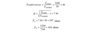
The unloaded Q = 7.94, and the reactance required for the inductor at the design frequency is 397 ohms. The reactance required for the capacitor is 403 ohms. If we were designing for 40m, we would calculate the inductance and capacitance from the reactance formulas at, for example, 7.050 MHz.

The same procedure would be followed to calculate the component values for the 80m band. We leave that computation as an exercise for the reader.
Construction
The 40m matching network was constructed so that it can be converted to 80m by moving the coil tap and changing the capacitor from approximately 50 pf to approximately 100 pf. The network is intended for use with a 600W linear amplifier. The inductor for this network consists of a 3″ long x 2″ DIA air coil, #16 AWG, 9 turns per inch [3]. The doorknob capacitor is an HEC HT50 NPO characteristic 50 pf +/-10% at 7.5 kV [4]. The capacitor in the photo was measured on an HP4262A LCR meter. It measures 53.6 pf. All of the components were found on eBay, but references have been provided for all new materials. The L-Network is in the lowpass configuration: series inductor followed by shunt capacitor, Figure 1. You may recall from matching topology that if the shunt element is close to the load, the match is from low to high impedance – in this case from 50 ohms to 3200 ohms. The turns of the coil were shorted at the cold end of the coil at 16T. The inductance of the remaining portion of the coil is approximately 9.4 μH. The network is housed in a Bud Industries PN-1328-DGMB ABS box [5]. The 1/4″-20 screw terminal on the left end of the enclosure, Figure 2, has been provided for a counterpoise connection. Counterpoises were covered in an earlier post [6]. The screw terminal has been connected internally to the coax shield at the SO-239 connector. The 1/4″-20 antenna terminal is located on the right end of the enclosure as shown in Figure 2.
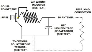
Figure 1. Convertible L-Matching Network Wiring Diagram. The moveable tap, optional counterpoise connection, and test load connection points are shown.
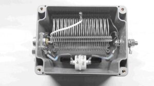

Figure 2. (Top) Convertible L-Matching Network for 40 and 80m. For 40m operation the inductor is tapped at approximately 16 turns from the cold end, and the HEC doorknob capacitor is approximately 50 pf. The inductor tap can be moved and the capacitor may be changed to convert from 40m to 80m operation. When an antenna analyzer is available, the conversion can be performed in minutes. (Bottom) L-Network Side View. The tapped inductor and HEC high voltage doorknob capacitor is visible. The UHF connector and counterpoise stud are also visible.
By this time you have probably observed that the component values are not exactly as calculated. Many times the capacitor value will not be a standard value. This will result in a different load impedance than the design value. Since the high voltage capacitors are somewhat expensive, the objective was to find surplus capacitors on eBay. If more exact values are required, contact HEC, and they will see if they can find something close to what you need.
Test
The network was evaluated with a 3200-ohm non-inductive potentiometer load [7]. The antenna analyzer employed was an MFJ-226 [8]. The 1.2:1 bandwidth of the network under resistive load is 150 kHz, Figure 3. The turn loss at 7.062 MHz exceeds 48 dB, Figure 4. The Smith Chart in Figure 5 displays an excellent match for a 3200-ohm non-reactive load. Figure 6 shows the corresponding reactance of 0.03 ohms at 7.062 MHZ.
 Figure 3. VSWR Plot. The 40m L-network is swept across the entire band illustrating better than 2.0:1 performance over the entire band.
 Figure 4. Return Loss Plot. The return loss at 7.062 MHz is better than 48 dB.
 Figure 5. Smith Chart Plot. The L-network is swept over the entire 40m band exhibiting an excellent match.
 Figure 6. Reactance Plot. The reactance zero crossing is at 7.062 MHz.
Operation
If a counterpoise wire is used, a common mode choke should be positioned at the matching network SO-239 connector. If no counterpoise wire is employed, a common mode choke should be positioned in the coax at a distance of 2m (6.56′) from the SO-239 connector for 40m operation. For 80m operation, that number should be doubled. It should be possible to ground the counterpoise terminal to a nearby ground rod if the antenna is configured as an inverted-L, but that configuration has not been evaluated. The voltage gradient on the inductor increases toward the antenna end of the inductor. A ceramic insulator was not required at the antenna terminal because input power is limited to 600W.
References
[1] Blustine, M., Highly Efficient L-Matching Networks for End-Fed Half-Wave Antennas, June 11, 2022.
https://www.n1fd.org/2022/06/11/l-matching-networks/
[2] Ibid.
[3] https://www.bwantennas.com/coilcat.html
[4] http://catalog.highenergycorp.com/category/ceramic-capacitors
[5] https://www.budind.com/product/nema-ip-rated-boxes/pn-series-nema-box/ip65-nema-4x-box-dark-gray-with-mounting-brackets-pn-1328-dgmb/#group=series-products&external_dimensions_group=0&internal_dimensions=0&indoor_outdoor_group=0&nema_rating_group=0&ip_rating_group=0
[6] Blustine, M., op. cit.
[7] https://www.jameco.com/z/3299Y-1-502VP-LF-Bourns-5K-ohm-1-2W-25-Turn-Cermet-Trimmer-Potentiometer_240590.html
[8] https://www.eham.net/reviews/view-product?id=12464